In the dynamic world of energy generation, turbines stand as colossal sentinels, tirelessly converting various forms of energy into the electricity that powers our modern lives. These engineering marvels play an indispensable role in our global energy landscape, propelling wind, water, steam, or gas through their mechanical veins to produce the vital electricity we rely on daily. However, with great power comes the need for steadfast guardians, and that’s where the Turbine Protection System (TPS) steps onto the stage.
The Turbine Protection System is an intricate web of sensors, algorithms, and safety measures that ensure the efficient and safe operation of turbines. This system not only maximizes power generation but also safeguards these colossal machines from the lurking threats that could lead to catastrophic failures.
In this blog, we embark on a journey into the heart of turbine technology to uncover the critical role played by Turbine Protection System.
Understanding Turbines
In the context of our exploration of Turbine Protection System (TPS), it is essential to first establish a solid foundation of knowledge regarding turbines themselves. This section, “Understanding Turbines,” aims to provide readers with a comprehensive overview of what turbines are, their fundamental principles of operation, and the various types of turbines commonly used in energy generation.
Turbines Definition
Turbines are mechanical devices designed to convert kinetic energy from a fluid (such as air, water, steam, or gas) into mechanical work or electricity. At their core, turbines are energy converters, taking the form of intricate machinery with one primary purpose: to harness the power of moving fluids and transform it into a usable and often essential source of energy.
Basic Working Principles of Turbine
The operation of turbines is founded on a few fundamental principles
Fluid Flow: Turbines are fundamentally reliant on the flow of a fluid, whether it’s the steam in a power plant, the wind in a wind farm, or the exhaust gasses in a gas turbine. The fluid’s kinetic energy is what drives the turbine’s motion.
Rotor and Blades: Central to the operation of a turbine is its rotor, which consists of blades or buckets. As the fluid flows over these blades, it exerts force, causing the rotor to rotate.
Energy Conversion: This rotation is where the magic happens. The kinetic energy of the fluid is converted into mechanical work, which can be used directly or, in many cases, to generate electricity via a connected generator.
Types of Turbines
Turbines come in various forms, each uniquely designed to harness different sources of energy. Here is the list of most popular turbines are:
- Steam Turbines
- Gas Turbines
- Wind Turbines
- Hydro Turbines
- Turboprop and Turbofan Engines
Here, we explore the most common types of turbines, shedding light on their distinctive features and applications:
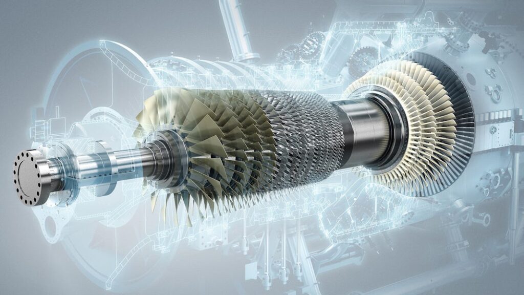
Steam Turbines: Steam turbines have been at the heart of power generation for over a century. They operate by directing high-pressure steam onto a set of blades attached to a rotor. As the steam flows over the blades, it causes them to rotate, driving a generator to produce electricity. Steam turbines are commonly found in fossil fuel power plants and nuclear facilities, where the heat generated from burning fuel or nuclear reactions is used to produce steam.
Gas Turbines: Gas turbines, also known as combustion turbines, are renowned for their versatility. These turbines are widely used in aviation for jet propulsion and in power generation, where they burn natural gas, diesel, or other fuels to produce a high-speed exhaust gas. The force of the gas exiting the turbine spins the rotor, generating power. Gas turbines are known for their rapid start-up times and are often used in peaker plants, which provide electricity during periods of high demand.
Wind Turbines: Wind turbines have become iconic symbols of renewable energy. They harness the kinetic energy of the wind to turn their blades, which are connected to a generator. As the blades rotate, they produce electricity without emitting greenhouse gasses or depleting finite resources. Wind turbines can be found in onshore and offshore wind farms, contributing significantly to clean energy production.
Hydro Turbines: Hydro turbines, also known as water turbines, play a pivotal role in hydroelectric power plants. These turbines utilize the energy of flowing water to generate electricity. Depending on the design, hydro turbines can be categorized into various types, including Francis, Kaplan, and Pelton turbines. Their efficiency and environmental benefits make them a preferred choice for sustainable energy generation.
Turboprop and Turbofan Engines: These are used in aviation for propulsion. Turboprop engines combine a gas turbine with a propeller, providing the necessary thrust for regional and smaller aircraft. Turbofan engines, on the other hand, are used in commercial airliners and military aircraft, employing a combination of jet thrust and a fan for efficient propulsion.
Read more about Turbine Control System
The Role of Turbine Protection System
Turbine Protection System, often referred to simply as TPS, are sophisticated arrays of sensors, control mechanisms, and algorithms designed to monitor, manage, and safeguard turbines.
Their primary mission of TPS is ensuring the safety of both the turbine itself and the personnel working with it. TPS are designed to detect anomalies and respond swiftly to prevent potential catastrophic failures or accidents.
One of the remarkable aspects of Turbine Protection System is their vigilance. They operate round the clock, 24/7, monitoring the turbine’s health.
The Key Components of Turbine Protection System
Turbine Protection System consist of several integral components, each contributing to their overall functionality:
Processor of Turbine Protection System (TPS)
The protection system requires a robust controller to ensure a safe shutdown of the turbine during emergency situations. As an example one such controller is the S7-314C-2DP, which maintains high availability and the necessary performance capabilities for tasks like safeguarding steam turbines.

This controller collects data from different field sensors and status indicators, performs both open-loop and closed-loop control functions, sends the resulting commands to the turbine valves, and handles all functions at both group and individual device levels. Well-organized and rigorously tested control strategies are available to address various plant control scenarios. This user-friendly system is easily integrated into a distributed control system, capable of handling complex tasks within the high-performance range.
Further in the Turbine Emergency Trip System (ETS), these processors ensure high availability and fail-proof hardware with a triple modular redundancy architecture.
Sensors and Control Logic in Turbine Protection System
Various sensors are strategically placed throughout the turbine to measure parameters such as temperature, pressure, vibration, and fluid flow. These sensors continuously collect data, providing real-time information about the turbine’s condition.
Advanced control logic algorithms process the data from sensors. They compare the measured values against predetermined thresholds and trigger appropriate responses if any parameters deviate from the norm. This could include altering operational settings or initiating shutdown procedures.
Hydraulic Trip System in Turbine Protection System
All newly manufactured steam turbines now come equipped with state-of-the-art electronic trip systems, eliminating the need for traditional mechanical bolts to provide overspeed protection.
The mechanical upgrade involves a comprehensive replacement of the original equipment within a 2-out-of-3 or 2-out-of-4 algorithmic voting architecture. To facilitate efficient on-line testing and calibration, a pre-assembled panel is deployed, featuring triple-redundant field devices for each relevant parameter.
Many components within this system architecture are intentionally designed to enable on-line repair and, if necessary, replacement. In the newly implemented electronic control logic, each parameter input is continuously monitored and compared to a predefined trip limit. If any parameter exceeds its respective trip limit, the control system will promptly trigger the closure of all turbine valves.
Notably, due to the system’s capacity to compare, monitor, and raise alarms for transmitters, the need for separate on-line testing of these transmitters is eliminated. The Turbine Protection System (TPS) manages the inputs required to trigger a unit shutdown, effectively mimicking the role of the trip solenoid in the existing trip block assembly. A trip-reset input is provided to clear any latched trips.
The trip output of the TPS consists of six discrete outputs, with two originating from each processor. This configuration aligns with the setup of six emergency trip oil dump solenoids, organized in a ‘2-out-of-3 to trip’ arrangement.
Turbine Trip Solenoids in Turbine Protection System
These are specialized solenoids used in sets, and their arrangement is provided in the diagram. A turbine trip command is generated by the Turbine Protection System (TPS) or Emergency Trip System (ETS). This command is sent to all four solenoid-operated valves (SOVs). However, we have implemented a unique configuration to address the possibility of SOV malfunctions or sticking.
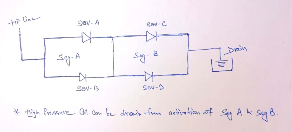
In order to initiate a turbine trip, it is necessary for at least one SOV to operate in each of the two sections (A or B), as indicated in the arrangement. To depressurize the high-pressure line in segment A, any one of the SOVs must operate, and likewise, in segment B, the activation of any one SOV is required.
Online Trip Solenoid Testing
As the turbine is running continuously and in turbine operation these trip valves are close. During the emergency condition when the turbine needs to be trip, functioning of these SOV is must so testing of trip SOV is mandatory during preventive maintenance of these valves.
For this purpose a special arrangement has been used as given in figure.
Safety Mechanisms and Communication interface of Turbine Protection System
TPS includes built-in safety mechanisms and emergency shutdown protocols. These are crucial for rapidly halting turbine operation in the event of a critical issue to prevent further damage or hazards.
TPS often have communication interfaces to relay data and alerts to plant operators and central control rooms. This enables timely decision-making and intervention when necessary.
Field Sensors / Instruments used in Turbine Protection System
The following instruments / Sensors are installed and they provide inputs to the TPS.
Vacuum Switches / Transmitters (Condenser system)
In the field, there are three vacuum pressure measurement devices. These devices offer both discrete contact and analog 4-20mA signal outputs. They can be connected to the TPS in either configuration. When they detect a high exhaust pressure (indicating low vacuum), the TPS will initiate a trip command.
Bearing Lube Oil Pressure Switches / Transmitters
There are three pressure measurement devices available, offering both discrete contact and analog 4-20mA signal outputs. They can be connected to the TPS in either configuration. When these devices detect low bearing oil pressure, the TPS will trigger a trip command.
High Vibration, Axial Shift and other User define Trips in Turbine Protection System
These instruments are typically included within the Turbine Supervisory Instruments (TSI) package. In many turbine setups, you’ll find high-frequency vibration detection probes in use. Some well-known vibration monitoring systems include Bently Nevada 3500, Shinkawa VMS, and others.
Speed Sensing method in Turbine Protection System
The Magnetic Pick Up (MPU) probe or sensor is responsible for primary speed control. In addition, three speed probes are employed, utilizing a 2oo3 logic configuration for overspeed protection.
In the context of large turbines, overspeed protection operates on three distinct levels. The first level is OPC control, which triggers at 103% of the rated speed. At this point, it leads to the closure of control valves (GV & IV). The second level involves an electrical trip signal that activates at 108% of the rated speed. This signal originates from the generator protection panel and trips the turbine. The third and final level of protection is mechanical speed protection, which relies on a fly ball arrangement and is activated when the speed exceeds 110% of the rated speed.
Mechanical Overspeed Trip Assembly in Turbine Protection System
The mechanical overspeed trip assembly relies on a relatively simple design. These systems incorporate components such as a bushing, adjustment nut, plunger, and spring arrangement. When the spring is compressed, it increases the force required to surpass the spring’s resistance. The trip speed is determined by factors including the weight of the plunger, the spring’s force, the speed of operation, and the distance between the plunger and the trip lever.
Given that the desired trip speed, plunger weight, and plunger-to-trip-lever distance remain constant, the sole adjustable parameter is the spring force. Adjusting the trip speed involves adding or removing shims or repositioning the adjustment nut to vary the compression on the spring. However, these adjustments can only be made in Turbine Protection System, when the turbine is shut down.
Watch our Video on Turbine Protection System:
Conclusion
In summary, Turbine Protection System is the unsung heroes that ensure the safe and efficient operation of turbines. With their vigilant monitoring and rapid response capabilities, Turbine Protection System contribute to the reliability and safety of these critical energy generation assets.
General Interview Questions on Turbine Protection System (Emergency Trip System):
Q1. What is the primary purpose of an Emergency Trip System (ETS) within a Turbine Protection System?
Answer: The primary purpose of the Emergency Trip System (ETS) is to ensure the safe and rapid shutdown of the turbine in the event of critical conditions or emergencies to prevent damage and hazards.
Q2. How does the ETS differ from standard turbine protection system in terms of functionality and response time?
Answer: The ETS is designed to respond much faster and more aggressively to critical conditions compared to standard protection measures. It’s specifically engineered for rapid turbine shutdown in emergency situations.
Q3. Can you explain the key components of an Emergency Trip System and their respective functions in Turbine Protection System?
Answer: Key components include a robust controller for command generation, sensors for data collection, advanced control logic for decision-making, hydraulic trip systems for rapid shutdown, and safety redundancies for reliability.
Q4. What are the critical parameters that an ETS monitors in a steam turbine, and why are they significant?
Answer: Critical parameters include Vibration, Axial Shift, overspeed, exhaust pressure, Vacuum and bearing lube oil pressure. Monitoring these parameters is vital because deviations can lead to catastrophic turbine failures.
Q5. How does the ETS handle overspeed conditions, and what measures are in place to ensure a rapid and reliable turbine shutdown?
Answer: The ETS uses electronic control logic to detect overspeed conditions. It initiates the closure of turbine valves and includes redundancies for reliable and rapid shutdown.
Q6. In the context of ETS, what is the significance of a trip-reset input, and how does it function?
Answer: The trip-reset input clears any latched trips, allowing the turbine to resume operation after a shutdown. It’s an essential component for controlled restarts.
Q7. What role does the hydraulic trip subsystem play in the Emergency Trip System, and how does it replace traditional mechanical overspeed protection in Turbine Protection System?
Answer: The hydraulic trip subsystem replaces mechanical overspeed protection by providing a more efficient and reliable means of shutting down the turbine during an overspeed condition.
Q8. What types of sensors are typically integrated into the ETS to provide real-time data for monitoring turbine conditions?**
Answer: Sensors commonly used include overspeed sensors, exhaust pressure and temperature sensors, bearing lube oil pressure sensors, and high-frequency vibration detection probes etc.
Q9. Can you explain the role of a Turbine Trip Solenoid in the ETS, and how does it ensure the trip command is executed efficiently?
Answer: Turbine Trip Solenoids operate as valves that execute the trip command. Their unique arrangement ensures an efficient turbine trip even after operation of any one solenoid in each section. (refer “Trip SOV” figure)
Q10. What safety redundancies are incorporated into the ETS to ensure its reliability, especially during critical turbine conditions?
Answer: Redundancies include triple-modular redundancy architecture, on-line testing and calibration, and triple-redundant field devices, all aimed at enhancing system reliability.
Q11. How are field instruments like vacuum switches and bearing lube oil pressure switches utilized in the ETS, and what do they monitor?
Answer: Vacuum switches monitor exhaust pressure, while bearing lube oil pressure switches monitor the pressure of the lubricating oil for bearings. Both are critical for detecting issues.
Q12. What communication interfaces or protocols are commonly used in the ETS to relay data and alerts to operators and control rooms?
Answer: Common communication interfaces include Ethernet, Modbus, or other industrial communication protocols, allowing real-time data and alerts to be transmitted to control rooms.
Q13. Can the Emergency Trip System be configured to accommodate different types and sizes of turbines, and what considerations are involved in this process?
Answer: Yes, the ETS can be customized to accommodate different turbines. Considerations include turbine type, size, operational conditions, and specific protection requirements.
Q14. Are there any industry standards or regulations that govern the design and implementation of Turbine Protection System, including the Emergency Trip System?
Answer: Yes, various industry standards and regulations, such as those from organizations like the International Electrotechnical Commission (IEC) and American Petroleum Institute (API), guide the design and implementation of Turbine Protection System.
Q15. In the event of a fault or malfunction within the ETS, what diagnostic and troubleshooting measures are typically employed to identify and rectify issues promptly?
Answer: Diagnostic measures include system self-tests and on-line repair capabilities. Troubleshooting involves checking sensors, control logic, and communication interfaces to identify and rectify faults.
#Turbine Protection System