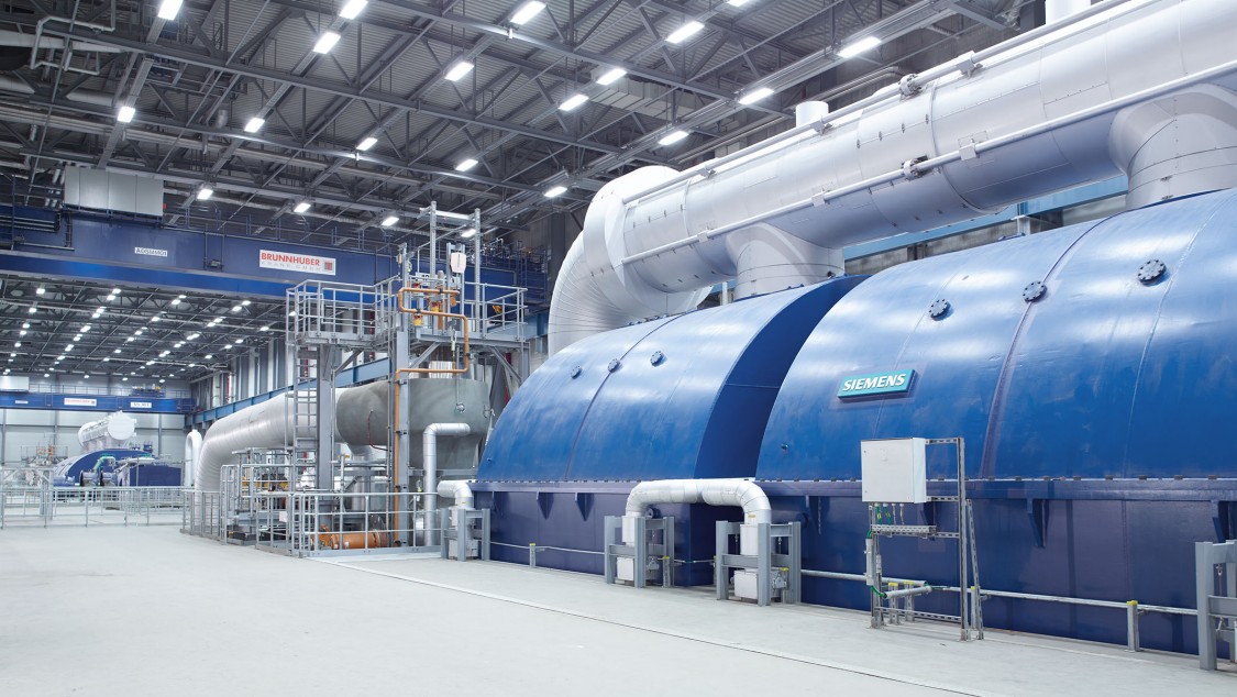
In the ever-evolving world of power generation, the pursuit of efficiency and reliability has always been paramount. Steam turbines, the workhorses of countless power plants, are no exception to this rule. What’s particularly intriguing is how the quest for better performance in steam turbines has taken a transformative turn over the years. As older turbines continue to defy their original life expectancies, the importance of precise control becomes increasingly evident.
Since the early 1980s, digital controls have emerged as the gold standard in numerous North American and European manufacturing and process industries. Recent advancements in digital processing technology, such as faster speeds, reduced costs, and more compact sizes, have firmly established digital turbine control as the technology of choice for power plant operators.
This transition represents not only a leap in efficiency but also a necessary response to the challenges posed by aging mechanical control systems. The days of fly-ball governors and mechanical linkages are giving way to a new era, one driven by digital precision. Join us as we delve deeper into this fascinating transformation and explore the compelling reasons why embracing digital turbine control is crucial for the future of power generation.
Turbine Control Philosophy / Governing Control
The cutting-edge digital turbine control system (TCS) has been meticulously engineered to exert precise control over the primary steam flow to the steam turbine under a myriad of operational scenarios. This control is expertly executed through the modulation of the turbine’s throttle, governor, admission, and extraction control valves. Within the TCS, these control functions are seamlessly orchestrated by employing simplex or redundant electronic processes, seamlessly woven into the fabric of both the software and hardware components. This intricate ballet is artfully performed by servo coil actuators.
Moreover, the TCS is not merely a passive observer but a proactive guardian of the turbine’s well-being. Master controllers spring into action as required, ensuring that the rates of change align harmoniously with the turbine’s prevailing mode of operation. With setpoint controls, open and closed-loop control functions, and continuous monitoring mechanisms at its disposal, the TCS steadfastly prevents the turbine generator from venturing into perilous operational territories. By doing so, it obviates the need for the turbine protection equipment to intervene and, in the process, averts potential damage to this invaluable machinery. This approach forms the bedrock of the overarching operational philosophy that underpins the high availability criteria of the turbine generator.

Crucially, the Turbine Control System is designed to encompass each of these vital functions as part of its standard package. However, it also offers the flexibility to selectively inhibit specific functions when necessary, facilitating seamless integration within the existing Distributed Control System (DCS) as per the unique requirements of the system.
Here are the main features of the Turbine Control system:
- Rotor Speed Control
- Inlet Pressure Control, (by boiler follow mode or turbine follow mode)
- Load Control, There are three ways to control generator load.
- By a load setpoint command from a DCS.
- By megawatt (MW) feedback to the load control function developed within TCS,
- By stand-alone operation as a MW or Speed Droop function.
- Turbine Stress Evaluator
- Frequency Influence (FGMA / RGMA)
- ADS (Automatic Dispatch System) Control
- Valve opening / lift Control
The TCS system is designed to keep the steam turbine stable in all situations, whether it’s starting up, shutting down, running alongside other power sources, or operating on its own. In cases where there’s a sudden power loss from the grid, like when lightning strikes, the TCS steps in to prevent the turbine from spinning too fast and causing damage.
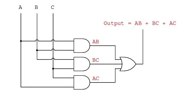
Within the TCS’s standard setup, there are smart algorithms in the master controller that can decide what to do based on input from different devices. It’s like having multiple sensors and switches that vote on the best course of action (2oo3 or 2oo4 logic) . If needed, some of these inputs can be turned off using a special password-protected control station.
In critical situations, the system can automatically turn off an input if it’s not working correctly. It then lets the operator know there’s a problem and switches to a backup. When the issue is fixed, the system goes back to using the original input to make sure everything runs smoothly.
The TCS should also be able to shut down automatically or manually. In auto mode, it gradually reduces power until it’s safe to turn off the generator. In manual mode, the operator takes control and turns off the generator when it’s ready.
Based on the features of the turbine governing system mentioned earlier, the TCS Software System includes the following standard master controllers:
1. Speed Controller:
The speed control function in the TCS system is crucial for managing the turbine’s speed during various operational phases. It oversees speed limits and acceleration across the entire speed range, working hand in hand with load changes, turbine trips, and more. This function can receive input from up to three speed probes, and it uses clever voting algorithms to prevent overspeed situations. If one input fails, the system automatically switches to a backup (due to 2oo3 logic), alarms the operator about the problem, and keeps the unit running smoothly. When the issue is resolved, the system seamlessly goes back to using the original input.
In power generation scenarios, when the generator is connected to the grid and the turbine controller is in “load” control mode, the speed control function continues to provide a speed error input to help maintain frequency stability. It does this by comparing the desired speed with the actual speed and adjusting accordingly, with high precision. The operator can manually select the desired speed reference from the control station.
Additionally, the rate at which the speed changes (ramp rate) can be set manually or automatically. Other parameters like how quickly the speed changes, how the turbine and boiler interact, and more, are fully adjustable through the Engineering Station.
During startup, the TCS offers four standard modes under speed control:
- The operator can set a speed target, and the unit will gradually reach that speed at a programmable rate. The operator can also manually adjust the speed up or down.
- In speed control mode, if the operator tries to stop the unit during a critical state, it will continue to change speed until it reaches a safe threshold.
- Depending on the turbine and its application, the TCS can be configured to warm up the unit without stopping it (during turbine rolling). This includes controlling the governor and stop valves to maintain a minimum speed.
- The system can also be set up according to a Standard Operating Procedure (SOP) provided by the customer. This involves ramping up to setpoints and holding them for specific times, ensuring the unit never stops within critical ranges.
The TCS includes features for smooth transitions between different modes of admission (full arc and partial arc) control and can conduct controlled tests of overspeed protection devices. It can coast up or down to the match rated speed (to match grid frequency). Once at synchronous speed, the controller accepts commands for synchronization, both manually and automatically.
2. Pressure Controller (Inlet/Admission):
The inlet or admission pressure control is a system that offers a choice between two channels to manage the steam entering the turbine. These channels serve two main functions: initial pressure control (also known as boiler follow mode) and limit pressure control (referred to as turbine follow mode).
This control function operates automatically and comes into play when the inlet steam pressure falls to a pre-defined and adjustable setpoint. Essentially, it kicks in when there’s a change in the incoming steam pressure.
This system gives the operator the flexibility to engage in sliding pressure control, particularly useful when the power output needs to be reduced to lower megawatt (MW) levels. In simpler terms, it allows for a smoother adjustment of power output by altering the pressure of the steam entering the turbine, ensuring efficient operation even at lower power levels.
3. Load Controller:
Once the turbine (generator) is connected to the power grid, the governing system / TCS can switch into the load control mode of operation either automatically or manually. In this mode, the load control function plays a crucial role in determining how much steam the turbine should receive. It does this by sending signals that adjust the position of servo valve actuators, regulating the steam flow.
The load control function relies on logic signals from the unit’s load control system (ULCS) to understand the operating conditions, such as imbalances in power load. The load reference (setpoint) represents the desired power output compared to the rated main steam pressure.
To change the desired power output, the operator simply sets a new target load and initiates the adjustment. The unit then ramps up or down at a predetermined rate, holding at the selected power level until a different command is given. This load reference can be adjusted either manually at the operator control panel or automatically through signals from the generator synchronization functions.
Additionally, the load control logic includes turbine runback control functions, which become active during abnormal conditions. These functions automatically reduce the power output to predetermined values using specific ramp rates and setpoint limits that can be adjusted with password protection.
Some of the standard turbine runback conditions are:
– Loss of boiler feed water pump
– Loss of condenser vacuum
– Loss of primary coolant/pump (generator H2 coolant circulating water pump etc)
Within the load control function, there’s also a load limiter that restricts how much the control valves can open, limiting the steam flow to the turbine. This load limit function is linked to the runback function so that any adjustment to the load limit automatically adjusts the load reference setpoint to a level slightly above the set load limit.
This prevents sudden load increases when the load limit function is corrected, like when a circuit breaker for a boiler feed water pump is accidentally switched off and then turned back on. The load limit can be configured across the entire operating range with password protection. The TCS provides an indication of how far the load limit is from being activated and gives a signal when it’s activated.
In cases where the generator breaker opens while under load, the TCS quickly closes the governor valves to minimize overshooting. This anticipatory action is triggered by the position of the generator breaker and is followed by reopening the valves to reach a preconfigured load rejection speed.
Moreover, there’s a megawatt (MW) feedback loop within the TCS load control function. It automatically adjusts the MW reference setting to match the actual real load in MW units. This correction is made by a controller that modifies the control valve signal to minimize MW deviations.
Lastly, the TCS includes an initial load pickup function (Min-load). This function involves a step increase (typically 3-5%) in power output each time the generator is initially synchronized to the grid. It’s designed to prevent reverse power conditions during synchronization.
An impulse pressure feedback loop is also part of the TCS load control function, correcting the megawatt reference based on actual impulse pressure values to trim the control valve signal and reduce impulse pressure errors.
Resources: Basic of PID Controller
4. Turbine Stress Controller:
The TCS system is designed to incorporate information from a turbine stress evaluation (TSE) system in order to control and restrict the rate of acceleration and load changes. During the turbine’s start-up and shutdown phases, the TSE system utilizes data derived from the difference in temperature readings from two thermocouples placed within the main stop valve (MSV, also known as the throttle valve) and the main control valve (MCV, also known as the governor valve).
This data is used to determine the limits on how quickly the turbine can accelerate or decelerate, and these limits are then imposed by the master controllers.
In typical operational scenarios with normal load conditions, the TSE system uses data from the temperature difference measured by thermocouples within the turbine casing, usually at the high-pressure (HP) and intermediate-pressure (IP) stages. This temperature deviation signal is employed by the master controllers to control and restrict the rate at which the load on the turbine changes.
5. Frequency Controller:
When the generator is connected to the power grid and the turbine controller is operating in the “load” control mode, the speed control function remains active, supplying a speed error signal that is utilized for maintaining frequency regulation. This speed error signal is obtained by comparing the desired speed reference with the actual speed of the system. The accuracy of frequency detection is maintained within a range of 10 millihertz (mHz), and there are adjustable parameters that allow control over the deadband and droop characteristics.
6. ADS (Automatic Dispatch System) Controller:
The TCS system is engineered to receive inputs from an ADS controller, enabling remote control of the machine’s loading and unloading along predefined ramp rates. The adjustable load limit gradients can be configured throughout the entire operational spectrum.
In most Independent Power Plants (IPPs), the ADS System is typically deactivated, allowing the operator to manually control the load based on specific operational needs.
7. Valve position Controller
The valve lift controller combines the minimum gated valve demand reference with the actual valve position (setpoint). Certain vendors offer standard applications that involve taking more than 20 samples per cycle during the valve’s movement to achieve the quickest response time possible.
Next, we will delve into TCS processors, as they are the sole entities responsible for guaranteeing the implementation of the features mentioned above.
The Turbine Control System (TCS) Processor
The core component of the steam turbine controller needs to be a fast digital processor. An illustrative example of such a processor is the S7 Programmable Logic Controller, specifically the S7-416, which is a robust processor with the necessary performance capabilities for tasks like controlling steam turbines.
The digital processor acquires data from sensors and status indicators through I/O channels, executes both open-loop and closed-loop control operations, transmits the resulting commands back to the I/O, and manages all functions at both group and individual device levels. Well-organized and rigorously tested control strategies should be accessible to address various plant control requirements. As an example, a specific application could offer a modular, fan less, cost-effective solution with extensive expansion and communication capabilities.
This user-friendly system enables straightforward implementation of a distributed structure capable of handling complex tasks in high-performance scenarios.
For more details watch our video:
Conclusion
The turbine control system is the hero of power generation and industrial processes, silently orchestrating the seamless operation of turbines that drive our world. It plays a pivotal role in maintaining optimal performance, ensuring safety, and responding to dynamic load demands. From monitoring speed and load to protecting against critical failures, the turbine control system’s capabilities are both intricate and vital.
Frequently Asked Interview Questions:
Further going forward here are some interview questions and its answers for a turbine control system:
Q1. Can you explain the primary function of a turbine control system?
Answer: The primary function of a turbine control system is to monitor and control the operation of a turbine to ensure safe and efficient performance. It regulates parameters like speed, load, and temperature, while also providing protection in case of abnormal conditions.
Q2. What are the key components of a turbine control system?
Answer: The key components typically include a controller (such as a PLC or DCS), sensors, actuators, a human-machine interface (HMI), hydraulic system and various software algorithms for control and protection.
Q3. How does the turbine control system manage speed and load control?
Answer: The turbine control system adjusts the steam or gas flow to the turbine and the position of control valves to maintain the desired speed and load. It does so by comparing reference values with actual turbine conditions and making real-time adjustments.
Q4. What is the importance of protection systems in a turbine control system?
Answer: Protection systems are crucial as they ensure the safety of the turbine and other associated equipment. They detect and respond to abnormalities like overspeed, overtemperature, or vibration to prevent damage and potential catastrophic failures.
Q5. What types of sensors are commonly used in turbine control systems, and what do they measure?
Answer: Common sensors include speed sensors (tachometers), temperature sensors (thermocouples and RTDs), pressure sensors, and vibration sensors. They measure parameters like turbine speed, exhaust gas temperature, steam pressure, and mechanical vibrations.
Q6. How does a turbine control system handle load changes and transient conditions?
Answer: Turbine control systems employ control algorithms to manage load changes smoothly. They can also include features like droop control to distribute load changes among multiple turbines in a power plant.
Q7. What is the significance of communication protocols in turbine control systems?
Answer: Communication protocols enable data exchange between different components of the control system. Common protocols include Modbus, Profibus, and OPC. Proper communication ensures seamless integration and coordination.
Q8. Can you explain the role of Human-Machine Interfaces (HMIs) in turbine control systems?
Answer: HMIs provide operators with a visual interface to monitor the turbine’s status, receive alarms, and make manual adjustments if necessary. They play a critical role in facilitating human intervention during abnormal conditions.
Q9. How does redundancy work in turbine control systems, and why is it important?
Answer: Redundancy involves duplicating critical components, such as controllers and sensors, to ensure system reliability. Redundancy is vital in preventing system failures and maintaining continuous operation.
Q10. What are some challenges or considerations when implementing a turbine control system in a power plant?
Answer: Challenges may include ensuring compatibility with existing systems, addressing cybersecurity concerns, and conducting thorough testing and validation to guarantee safe and efficient operation.
Resources: Steam Turbine Control System PPTs